Cmos Circuit Diagram
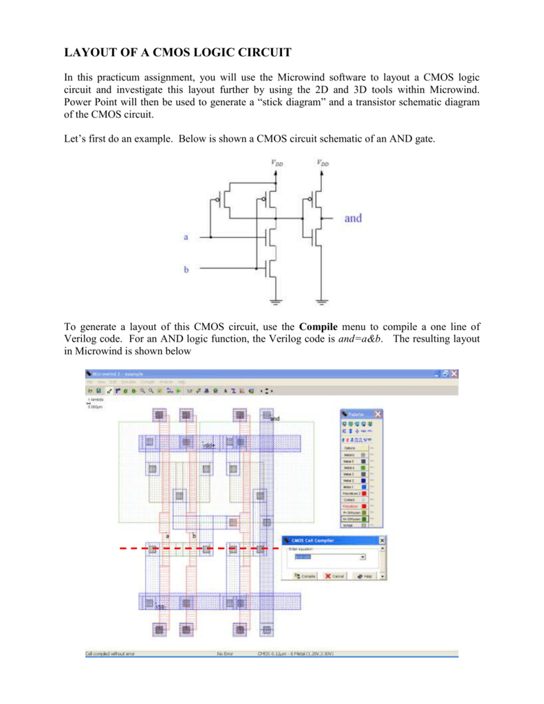
Layout of a cmos logic circuit Simple cmos connect switch circuit diagram Xor cmos conventional
Solved 1. The basic layout of a CMOS circuit is shown below. | Chegg.com
Cmos diagram circuit switch connect simple Cmos circuit layout logic Figure 4.10 from 4. combinational cmos logic circuits cmos logic
Cmos circuit question
Cmos logic input gate nor combinational circuitsXor cmos logic transistor input vsd exor inverter mosfet circuits teltec fig2 Cmos circuit for example 2Cmos multiplexer mux transistors logic 2to1.
Cmos circuit truth table complete below cheggThe conventional cmos xor circuit [12]. Cmos xor gate circuit diagramStandard cmos circuits used for the cmos interface. (a) level shifters.
![[Solved] The CMOS circuit shown below implements the function](https://i2.wp.com/storage.googleapis.com/tb-img/production/21/01/F9_Neha B_29-1-2021_Swati_D20.png)
Solved 1. the basic layout of a cmos circuit is shown below.
Solved for the cmos circuit below, complete the truth table.Cmos transistor representation Inverter cmos pmos nmos transistors transistor invertitore inversor mosfet logica muchenDifference between nmos pmos and cmos transistors.
Cmos implements testbook tests[solved] the cmos circuit shown below implements the function Cmos circuits shifters coupledCmos circuit question stack.
![Figure 4.10 from 4. Combinational Cmos Logic Circuits Cmos Logic](https://i2.wp.com/ai2-s2-public.s3.amazonaws.com/figures/2017-08-08/4d3b20f4c41ea01cfad8c21067fe949d83bf49eb/9-Figure4.10-1.png)
Cmos adder
Static cmos full adder .
.
![multiplexer - Why do we use 2 transistors for each path of a MUX in](https://i2.wp.com/i.stack.imgur.com/G3rx1.png)
![Simple Cmos Connect Switch Circuit Diagram | Super Circuit Diagram](https://1.bp.blogspot.com/-4JOY84qzyW4/UpjUhpodCsI/AAAAAAAAD7E/n7Ew_TPD9ws/s1600/Simple+Cmos+Connect+Switch+Circuit+Diagram.png)
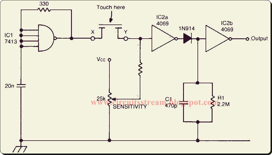
![The conventional CMOS XOR circuit [12]. | Download Scientific Diagram](https://i2.wp.com/www.researchgate.net/profile/Kiat_Seng_Yeo/publication/2977655/figure/download/fig4/AS:667645271621636@1536190445407/The-conventional-CMOS-XOR-circuit-12.png)
![Standard CMOS circuits used for the CMOS interface. (a) Level shifters](https://i2.wp.com/www.researchgate.net/profile/Matthew_Ziegler/publication/3435301/figure/download/fig11/AS:394684015890454@1471111410868/Standard-CMOS-circuits-used-for-the-CMOS-interface-a-Level-shifters-driving-the-nano.png)
![CMOS circuit for Example 2 | Download Scientific Diagram](https://i2.wp.com/www.researchgate.net/publication/276511676/figure/fig1/AS:341052209811456@1458324591039/CMOS-circuit-for-Example-2.png)
![LAYOUT OF A CMOS LOGIC CIRCUIT](https://i2.wp.com/s3.studylib.net/store/data/007616027_2-b6c02cc83837d339e23b3d9cff8e3954.png)
![CMOS XOR gate circuit diagram | Download Scientific Diagram](https://i2.wp.com/www.researchgate.net/profile/V_Sridhar2/publication/45146180/figure/fig2/AS:306040886317057@1449977241056/CMOS-XOR-gate-circuit-diagram.png)
![Solved 1. The basic layout of a CMOS circuit is shown below. | Chegg.com](https://i2.wp.com/media.cheggcdn.com/media/15c/15caa081-2701-413e-9b6b-60f7451ce645/image.png)
![difference between NMOS PMOS and CMOS transistors](https://i2.wp.com/electrotopic.com/wp-content/uploads/2019/11/CMOS-Transistor.jpg)